Making a Silicon Port mould
This has come about as part of the porting thread in the 6cyl section on Fordmods.com
http://www.fordmods.com/ford-4l-and-6-c ... 86312.html
At first we were asking for people to donate cracked, corroded and other wise junk heads to give us the ability to create a bit of a head library.
For the most part this is to sort the fact from the fiction regarding all the stories about which head is better ect. Getting heads also gives us the ability to modify flow test many individual changes with out needing to ruin good heads.
It's proven difficult to obtain heads even though a number of people have said they had junk heads and would donate them.
Taking moulds in the end works out cheaper, PLUS the chance is there to mould already ported heads to compare with out damage or down time.
Port moulding
What you will need.
500g fast set silicon. In this case I am using Pinkysil Bought online from http://www.amcsupplies.com.au
Small amount of dish liquid (free mould release)
A kitchen scale
A mixing cup
and a mixing spoon.
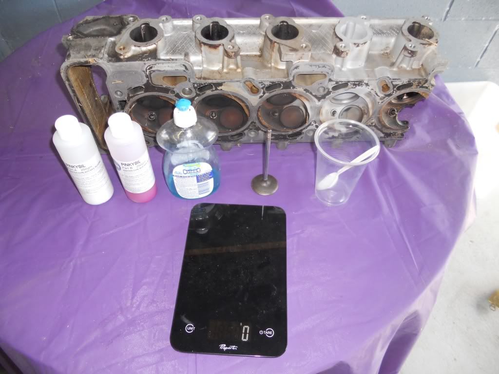
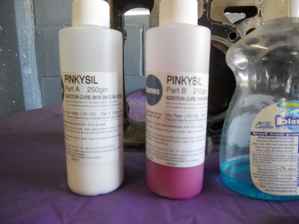
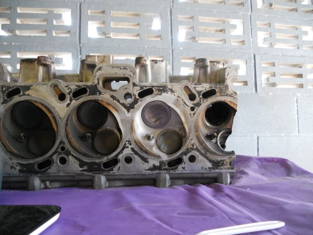
First step is clean the port and valve you are going to mould. Leave the valve stem seal in place as it will help to hold the valve in place.
Place the head on a plastic covered table with the exhaust ports facing down, You want the head reasonably level.
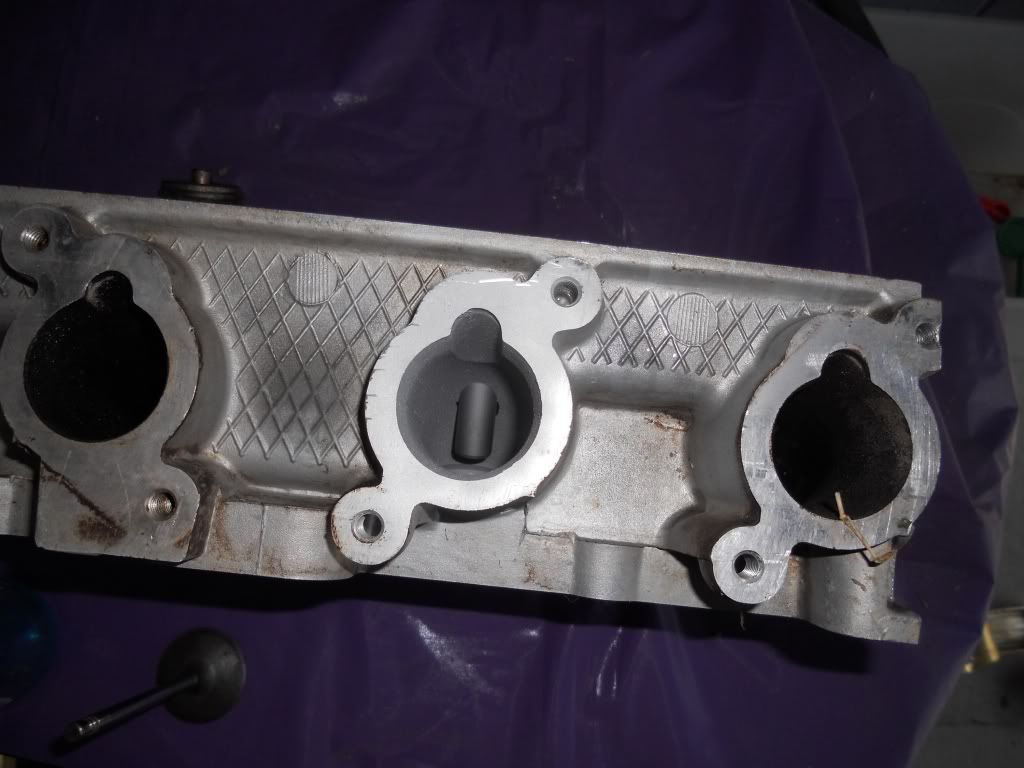
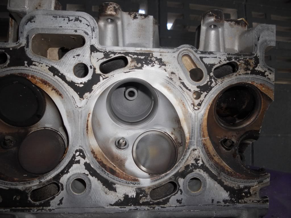
Put a small drop of dish liquid on your finger and coat the back of the valve and about 2cm of the stem.
Also coat as much of the port and valve guide as you can.
In doing this you do not want to wet the port with dish liquid, you only want a 'dry' coating.
Sorry no pic of this process.
Once done install the valve making sure it is seated firmly.
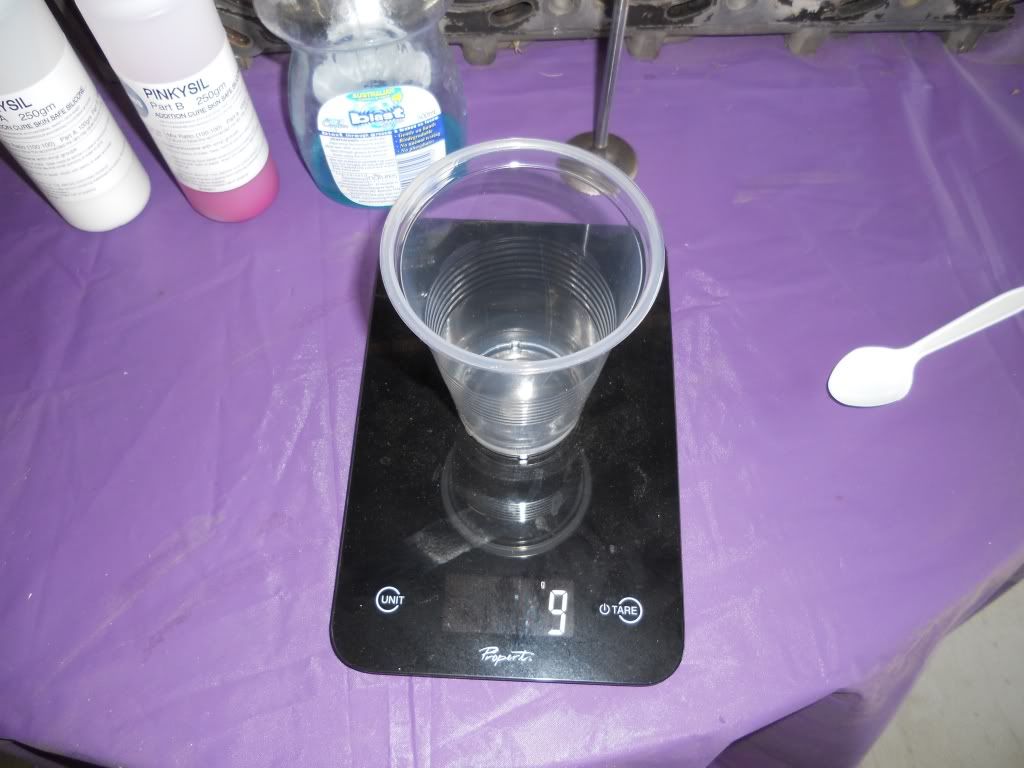
Place the cup on the scale.
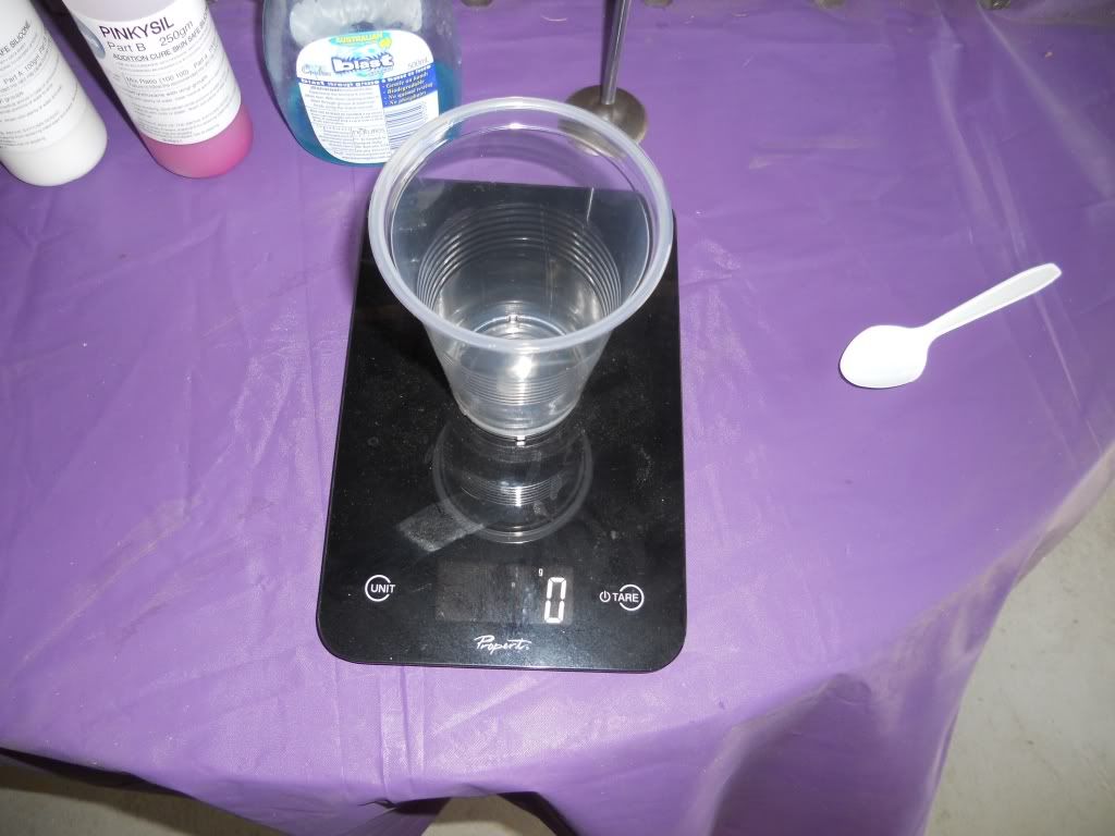
and then zero the scale
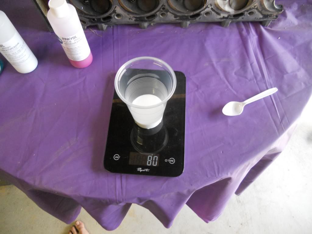
Slowly pour in 80 grams of PART A
Then aero the scale again.
Slowly pour in 80 grams of PART B
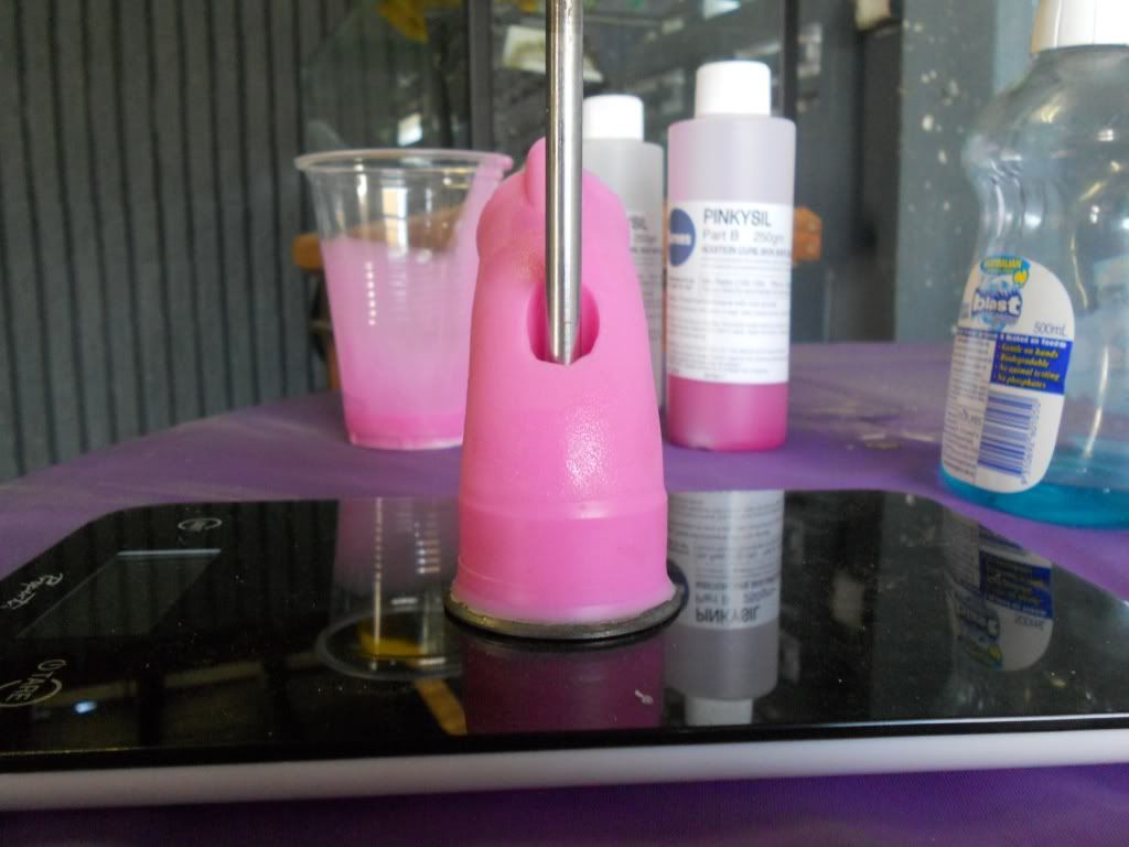
Mix thoroughly to get an even, consistent coulor. At this point as we are using a fast set silicon you only have at most ONE minute to get the mixing done other wise the silicon will start to set and you will be rushing to pour the now thick lumpy silicon before it's wasted. TRUST ME
Once mixed pour the silicon slowly into the port until full
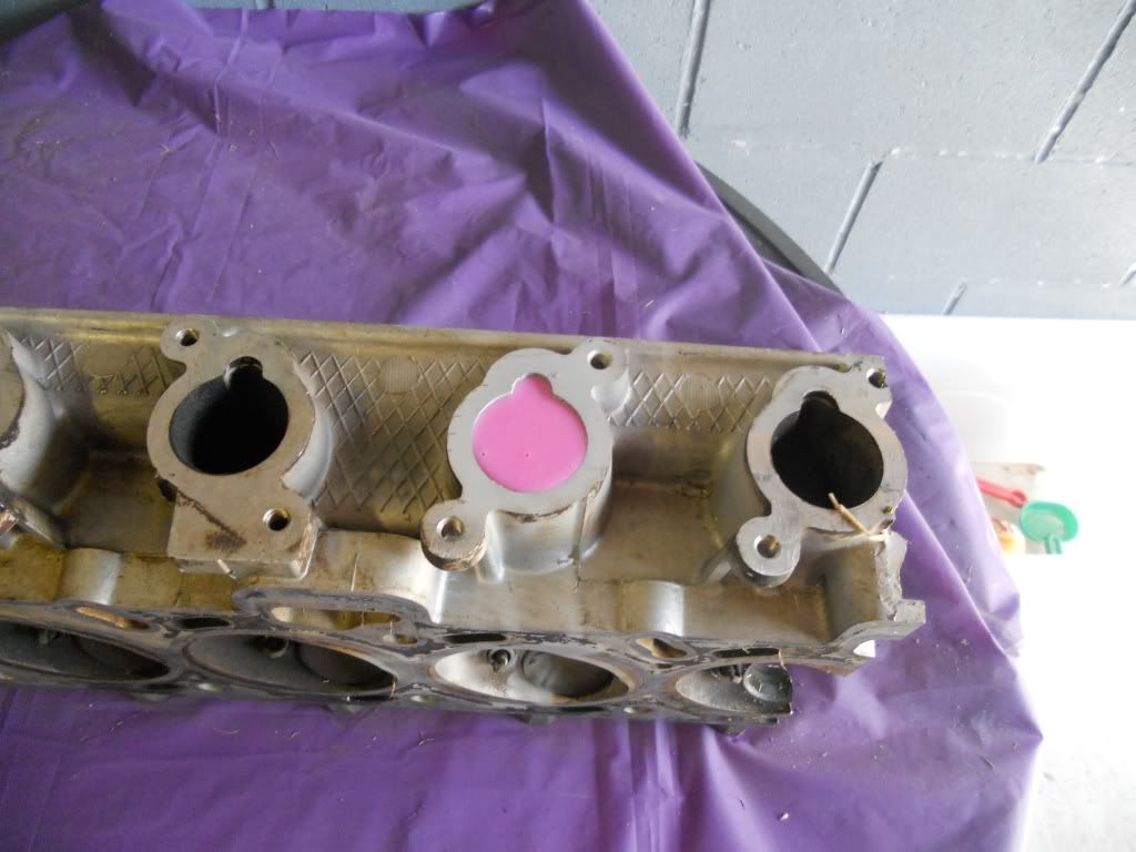
Depending on the head you are moulding, you'll have a little left over
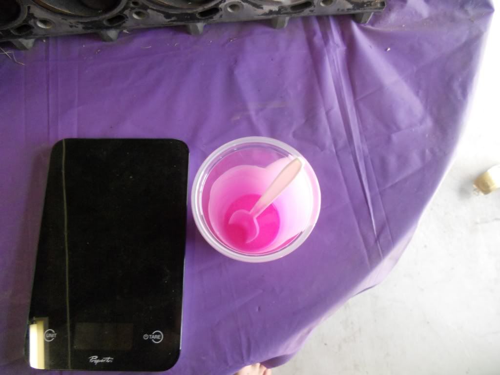
If you have a lead sinker moulds, now would be a good time for making some bright pink slingshot ammo
De-moulding
After 20 mins the mould is ready to come out.
Give the valve a tap to knock it loose and remove it.
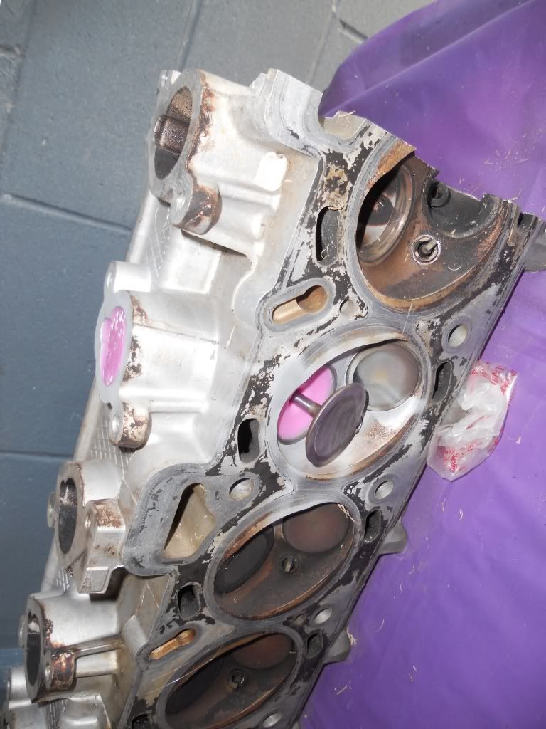
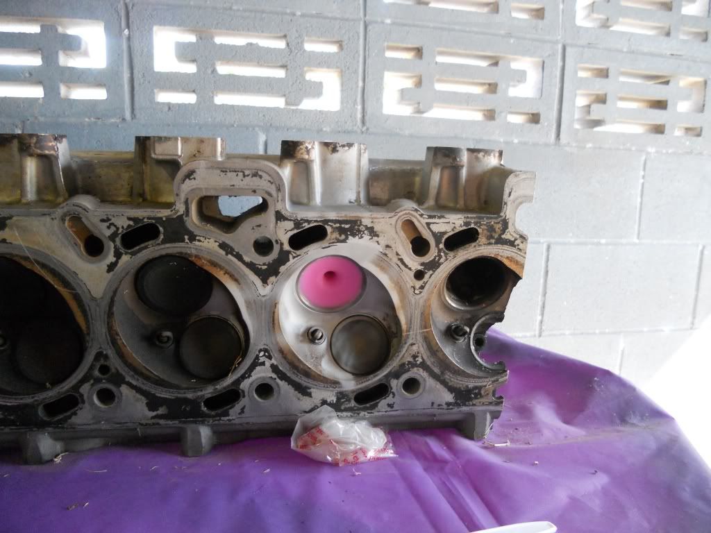
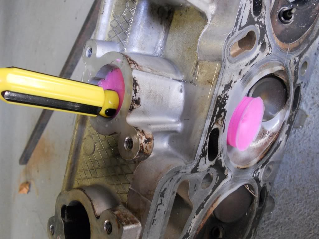
Insert a flat screw driver to gently pry the mould away from the port walls, do this right around the mould at both ends.
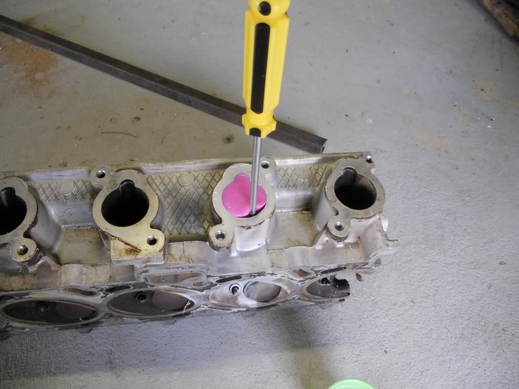
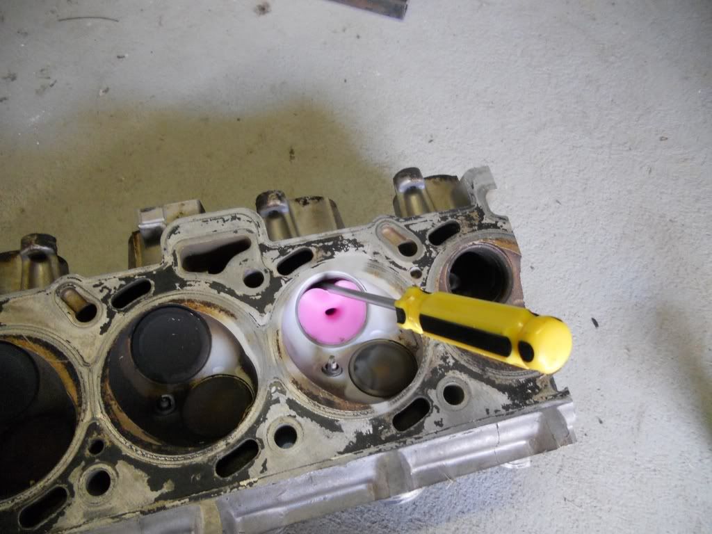
Mix a small amount of water and dish liquid and with the screw driver still inserted tip some into the gap, again all around and at both ends working the mould to get all of it soaked.
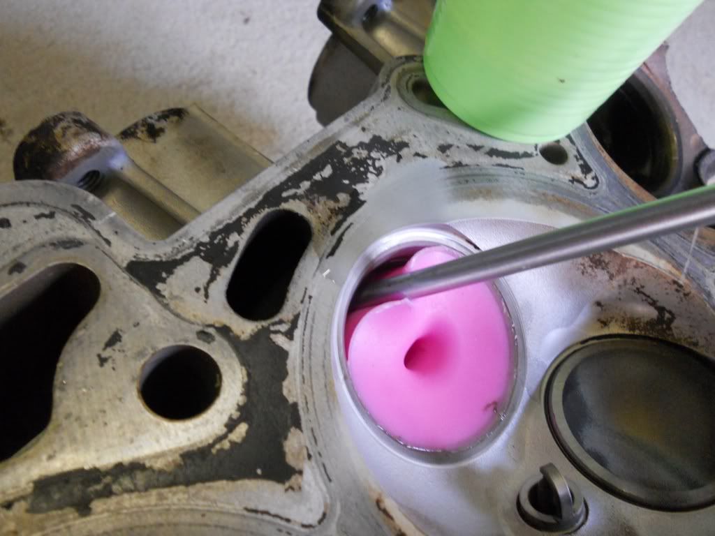
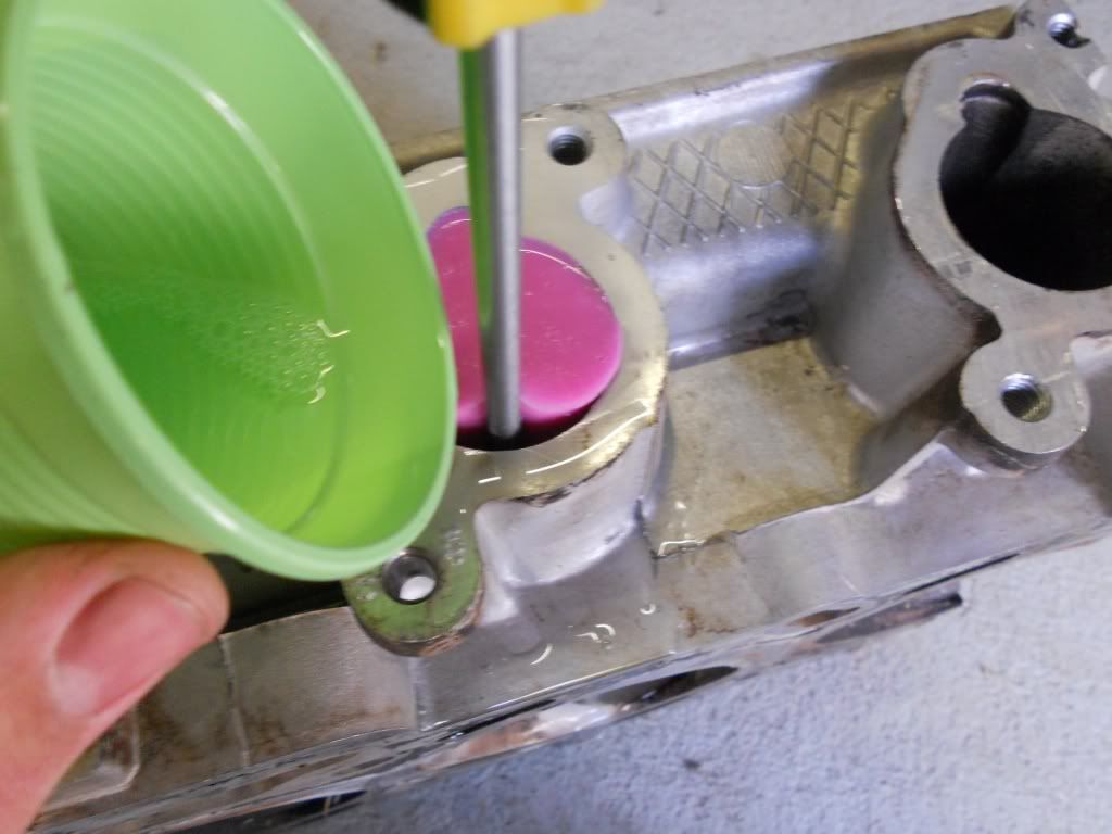
Now push from the manifold end with handle of the screw driver and push the mould out.
This may take a fair amount of force.
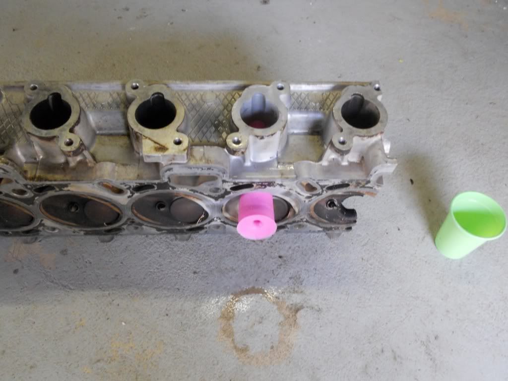
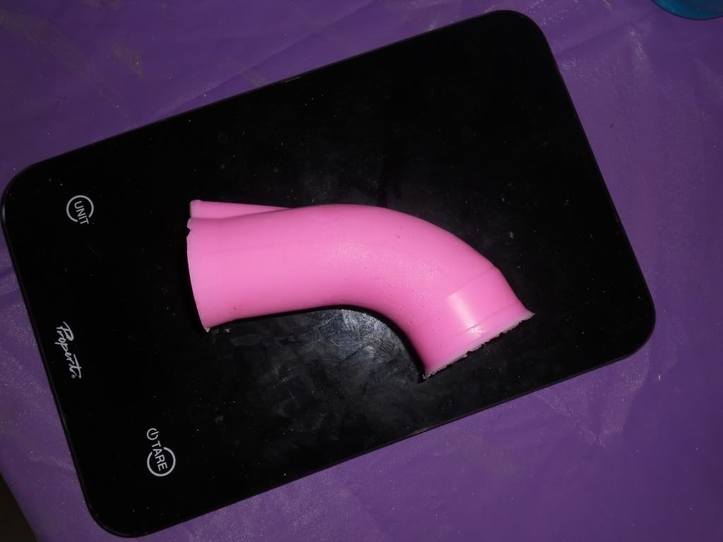
The finished mould
http://www.fordmods.com/ford-4l-and-6-c ... 86312.html
At first we were asking for people to donate cracked, corroded and other wise junk heads to give us the ability to create a bit of a head library.
For the most part this is to sort the fact from the fiction regarding all the stories about which head is better ect. Getting heads also gives us the ability to modify flow test many individual changes with out needing to ruin good heads.
It's proven difficult to obtain heads even though a number of people have said they had junk heads and would donate them.
Taking moulds in the end works out cheaper, PLUS the chance is there to mould already ported heads to compare with out damage or down time.
Port moulding
What you will need.
500g fast set silicon. In this case I am using Pinkysil Bought online from http://www.amcsupplies.com.au
Small amount of dish liquid (free mould release)
A kitchen scale
A mixing cup
and a mixing spoon.


First step is clean the port and valve you are going to mould. Leave the valve stem seal in place as it will help to hold the valve in place.
Place the head on a plastic covered table with the exhaust ports facing down, You want the head reasonably level.


Put a small drop of dish liquid on your finger and coat the back of the valve and about 2cm of the stem.
Also coat as much of the port and valve guide as you can.
In doing this you do not want to wet the port with dish liquid, you only want a 'dry' coating.
Sorry no pic of this process.
Once done install the valve making sure it is seated firmly.

Place the cup on the scale.

and then zero the scale

Slowly pour in 80 grams of PART A

Then aero the scale again.
Slowly pour in 80 grams of PART B
Mix thoroughly to get an even, consistent coulor. At this point as we are using a fast set silicon you only have at most ONE minute to get the mixing done other wise the silicon will start to set and you will be rushing to pour the now thick lumpy silicon before it's wasted. TRUST ME
Once mixed pour the silicon slowly into the port until full

Depending on the head you are moulding, you'll have a little left over

If you have a lead sinker moulds, now would be a good time for making some bright pink slingshot ammo
De-moulding
After 20 mins the mould is ready to come out.
Give the valve a tap to knock it loose and remove it.


Insert a flat screw driver to gently pry the mould away from the port walls, do this right around the mould at both ends.


Mix a small amount of water and dish liquid and with the screw driver still inserted tip some into the gap, again all around and at both ends working the mould to get all of it soaked.


Now push from the manifold end with handle of the screw driver and push the mould out.
This may take a fair amount of force.


The finished mould


