Another Outside link to one of my tutorials on Fordforums.com.au. This one's on replacing front brakes.
Front Brake Replacement *56k Warning
*edit. Oh that's right. Some of you got banned... see next post*
New front brakes - Now more than just a link
6 posts
• Page 1 of 1
New front brakes - Now more than just a link
Last edited by BLSTIC on July 20th, 2009, 8:49 pm, edited 2 times in total.
- BLSTIC
- Idling
- Posts: 90
- Joined: June 21st, 2009, 10:20 am
- Has Liked: 0 time
- Been Liked: 0 time
Re: New front brakes
I forgot half of you are banned from AFF.com.au. Below is from my fordforums post.
BLSTIC wrote:As Promised. Step By Step brake pad, disc, and wheelbearing replacement.
Front Brake Replacement – Discs, Pads, Wheel Bearings
Ok so you have established that your brakes are worn out, damaged, not up to your thrashing, spoil the looks of your mags, or are otherwise undesirable. This guide is the first stop on fixing that problem. It deals with replacement of the discs, pads, and wheel bearings on the front wheels. It is specific to EF Falcons, but the basic theory is similar for most cars with hydraulic disc brakes (most passenger cars this side of the moon landing).
1: Remove wheel.
Loosen the wheel nuts slightly. Jack up the car using the factory jacking point, or other strong point (chassis rails are great for this), and then lower it on to a jack stand. The wheel needs to be off the ground while the car is on the jack stand, so make sure you don’t go too low. Remove the wheel nuts, and pull the wheel off.
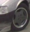
The scene should go from this:
To This:
2: Remove Calliper
There are two bolts, one at either end of the calliper. They have different diameters, so it’s extremely difficult to put them back in the wrong spot. The first is next to the bleed nipple (looks much like a grease nipple, but it doesn’t have a ball in the hole); the second is at the other end of the calliper. Remove them. Pull the calliper up, away from the disc. It might be a little stiff, but it will come eventually. Hopefully the scene looks like this:
The outboard pad slips down from the calliper, and the inboard has to come away from the piston before being removed.
3: Remove Disc.
Ok now you need to remove the dust cap. I neglected to get a picture of this still attached on the old disc, but I’m sure you’ll figure out what it is when you see the next pic. After removing it (Multi-Grips are the accepted way, but I had to LIGHTLY tap with a hammer, sideways, before prising them off with the multi-grips), you are faced with a split pin, a castle nut-cover, and the wheel bearing adjuster nut. Remove in that order and your front hub are looks like:
The next bit is simple. Pull the disc out lightly, supporting its weight. Remove the inner wheel bearing, and after a brief cleaning you are left with a bare hub. Like mine:
4: New Disc Installation.
Ok, now you are half way, it’s time to install the oil seal in the new (freshly cleaned) disc. Using a piece of conveniently sized pipe as a drift, lightly hammer the oil seal all the way home. It sits below the surface of the disc, so it is mildly difficult to get there. Like so:
Now it’s time for (clean) grease. This is the accepted method of greasing a wheel bearing. Note the grease coming through the rollers.
Now you can put the inner wheel bearing, disc, outer wheel bearing, thrust washer, and adjuster nut on, in that exact order. You can throw some extra grease in the middle if you want. The scene looks like this:
Now, using multi-grips (as it’s only low tension, and 28mm sockets are hard to come by), do the nut up reasonably (i.e. one medium hand) tight, to make sure everything is where it is supposed to be, undo the nut until it becomes free, and do it up again until a light drag can be felt while rotating the disc. Put the castle nut-retainer on, and put a new split pin through. The pin is installed so that, once through, one leg goes over the thread. Like this (but in focus):
Cut off the bottom leg with your side-cutters, and tap the dust cover on, after greasing the inside. This nut comes under the category of ‘Jesus Nut’. Ideally the scene is:
5: Grease Slides.
Ok now you need to grease the slides. First up, remove them. This is achieved by pulling the rubber boot off the end you wish to push them from, and pushing them through. The upper ones can only be removed one way, and the lower ones have a boot that can only be removed from the pin itself, not the calliper (while the pin is in, anyway). After removal and cleaning, cover them is specific brake grease. It isn’t harmful to rubber, doesn’t dilute in brake fluid, and appears to be expensive. Re-installation is by pushing the slides back in. The boots seemed to arrange themselves in the right spot for me.
6: New Pads:
Simple, just put anti-squeal on the back where there is pad-calliper (or anything) contact, wait 10 minutes, and install. During the 10 minute wait for the anti-squeal to set, push the piston back into the calliper. It is a REALLY good idea to take the cap off the reservoir and remove some fluid. To push the piston back into the calliper, use your old inner brake bad, and a G-Clamp. Once the piston is all the way in (and the anti-squeal has set), the calliper should resemble this:
Note that this amount of anti-squeal isn’t needed. I just squeezed too hard and decided it might as well go somewhere. I also don’t have mags that allow the calliper to be seen.
Now bolt the calliper back on (these two are also Jesus Bolts) after cleaning the disc and you can now see why people do this so often: Shiny Bits
After cleaning everything (again), putting the wheel back on, and checking that there is indeed no play in the wheel bearing, you can go drive normally. Leave the thrashing for about 300 city km, to allow the discs to go through a few heat cycles. Before you set out, press the brakes reasonably hard (while you aren’t moving) to get the discs in position. Note the lack of pedal that you would have had if you did this at a stop sign…
- BLSTIC
- Idling
- Posts: 90
- Joined: June 21st, 2009, 10:20 am
- Has Liked: 0 time
- Been Liked: 0 time
Re: New front brakes - Now more than just a link
Just a little bit of advice, the rotors are actually directional, and you have it on BACKWARDS.
This is in a mechanics shop, and is from a brake supplier

You will probably still notice with the brakes on as pictured in the tutorial that you still get brake fade, and rotors don't last as long.
Just thought I should share the info.
This is in a mechanics shop, and is from a brake supplier

You will probably still notice with the brakes on as pictured in the tutorial that you still get brake fade, and rotors don't last as long.
Just thought I should share the info.
-

DJV8T5 - Breaking Traction
- Posts: 1805
- Joined: March 2nd, 2011, 9:58 pm
- Location: Wodonga
- Has Liked: 216 times
- Been Liked: 88 times
Re: New front brakes - Now more than just a link
Not all slotted rotors have directional cooling.
iirc DBA slotted rotors are marked 'left' and 'right' and have the slots facing the direction shown in the tutorial. I think RDA are the same too.
That picture from AP Racing actually contradicts itself.
It says "slots and vanes always angle to the rear" yet the picture shows them as opposite.
iirc DBA slotted rotors are marked 'left' and 'right' and have the slots facing the direction shown in the tutorial. I think RDA are the same too.
That picture from AP Racing actually contradicts itself.
It says "slots and vanes always angle to the rear" yet the picture shows them as opposite.
-

MAD - Cruising
- Posts: 240
- Joined: September 22nd, 2008, 11:53 am
- Location: Cranbourne
- Has Liked: 6 times
- Been Liked: 19 times
Re: New front brakes - Now more than just a link
I have found that when the slots are angled as tutorial shows, that braking is not as enhanced as when they slots are facing as the poster shows
-

DJV8T5 - Breaking Traction
- Posts: 1805
- Joined: March 2nd, 2011, 9:58 pm
- Location: Wodonga
- Has Liked: 216 times
- Been Liked: 88 times
Re: New front brakes - Now more than just a link
that diagram is also refering to the internal vanes which are more important to cooling than the slots on the outside which just remove the gases from between pad and rotor, dba have a different vane set up
245rwkw @ 8psi EF Fairmont- HX35 turbo, 42lb lucas injectors, 45mm wastegate, owner made exhaust manifold cooler piping, port and polish, 3" exhaust, super lows, 17x8.5 ROH z's, shift kit, XR8 bulge and extra vents, slotted rotors, J3 boost tune, wrx seats, wideband.... brake upgrade to come
-

Bob Lablaw - Spooling Up
- Posts: 507
- Joined: September 4th, 2009, 6:49 pm
- Location: Rotorua, NZ
- Has Liked: 17 times
- Been Liked: 30 times
1996 Ford Fairmont Ghia
6 posts
• Page 1 of 1
Who is online
Users browsing this forum: No registered users


