Making a Silicon Port mould

Walk throughs on modifcations

Making a Silicon Port mould

Postby brad_m » September 25th, 2011, 8:27 pm : SNR Likes this post

This has come about as part of the porting thread in the 6cyl section on Fordmods.com
http://www.fordmods.com/ford-4l-and-6-c ... 86312.html
At first we were asking for people to donate cracked, corroded and other wise junk heads to give us the ability to create a bit of a head library.
For the most part this is to sort the fact from the fiction regarding all the stories about which head is better ect. Getting heads also gives us the ability to modify flow test many individual changes with out needing to ruin good heads.
It's proven difficult to obtain heads even though a number of people have said they had junk heads and would donate them.
Taking moulds in the end works out cheaper, PLUS the chance is there to mould already ported heads to compare with out damage or down time.


Port moulding

What you will need.
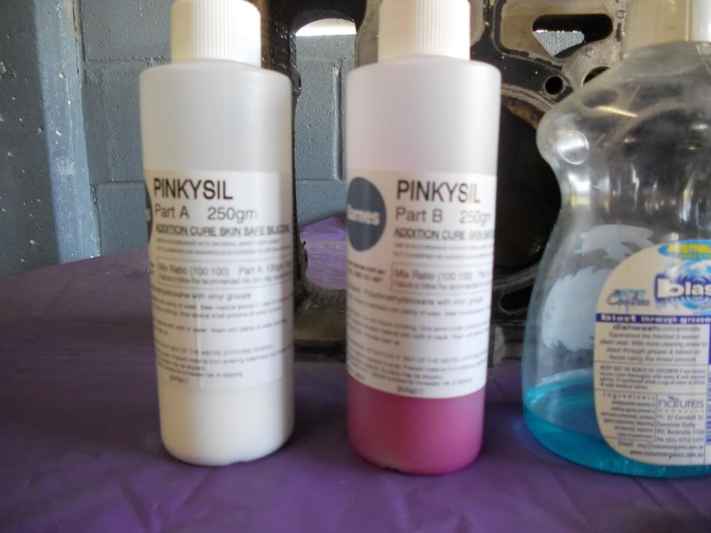
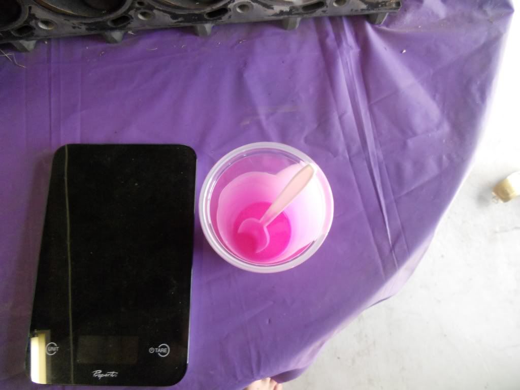
500g fast set silicon. In this case I am using Pinkysil Bought online from http://www.amcsupplies.com.au
Small amount of dish liquid (free mould release)
A kitchen scale
A mixing cup
and a mixing spoon.
Image
Image


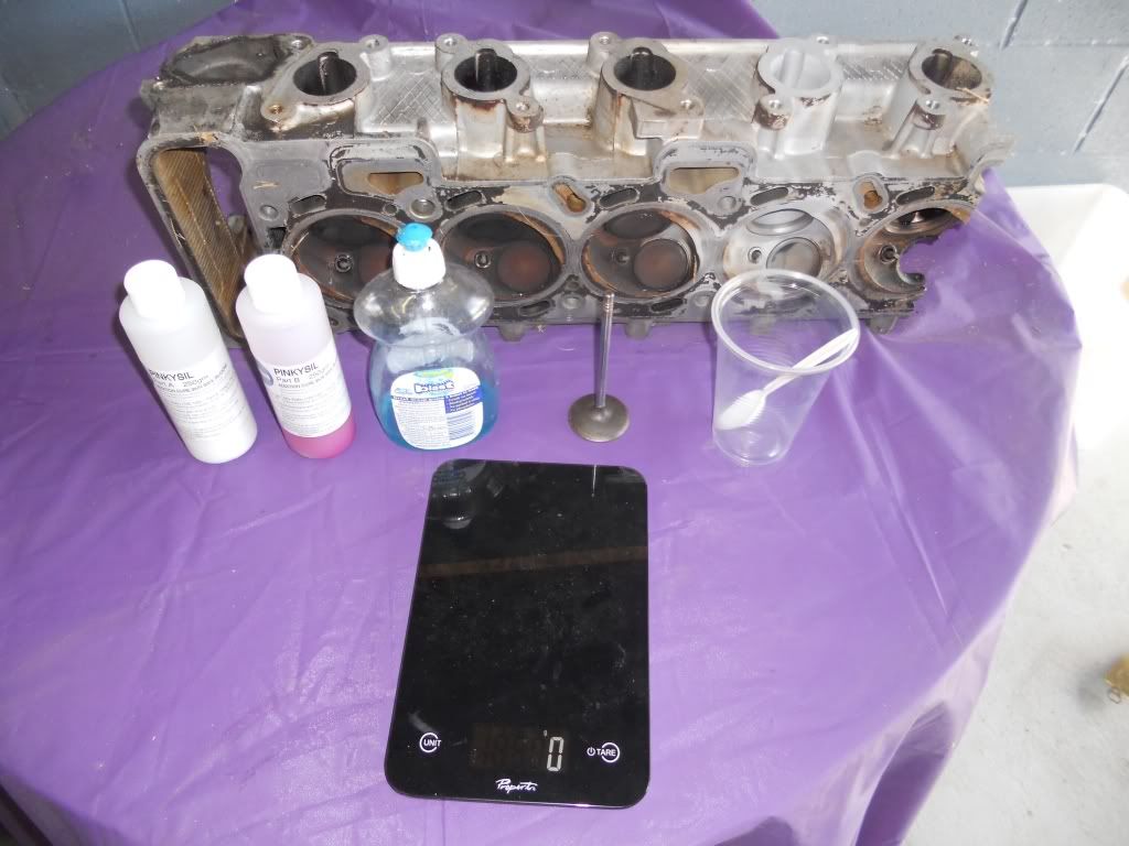
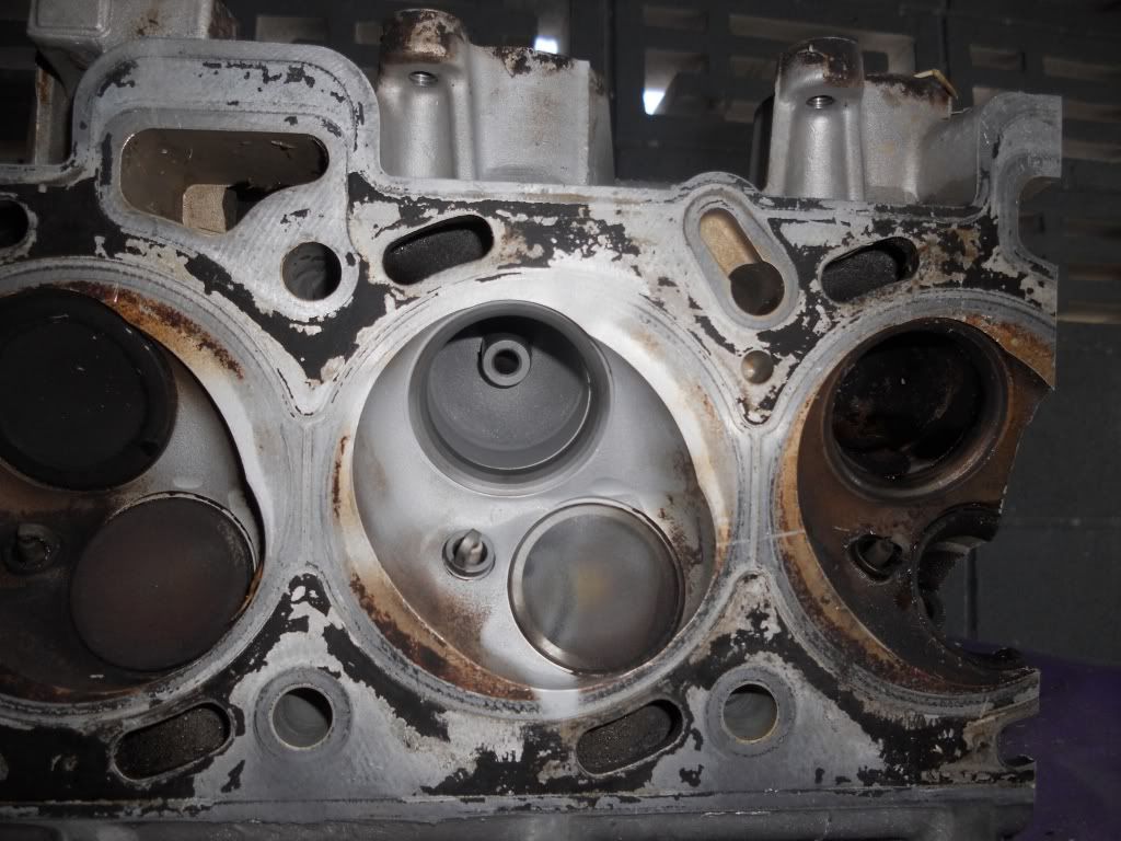
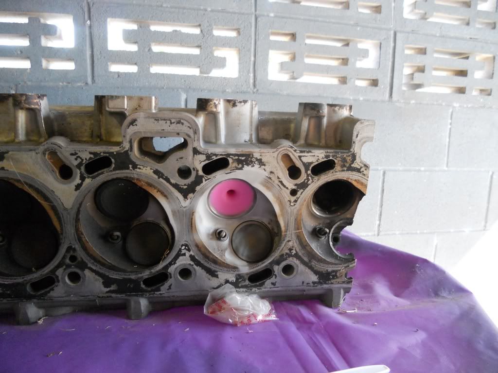
First step is clean the port and valve you are going to mould. Leave the valve stem seal in place as it will help to hold the valve in place.
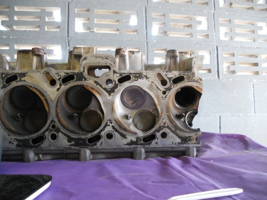
Place the head on a plastic covered table with the exhaust ports facing down, You want the head reasonably level.
Image
Image


Put a small drop of dish liquid on your finger and coat the back of the valve and about 2cm of the stem.
Also coat as much of the port and valve guide as you can.
In doing this you do not want to wet the port with dish liquid, you only want a 'dry' coating.
Sorry no pic of this process.

Once done install the valve making sure it is seated firmly.
Image


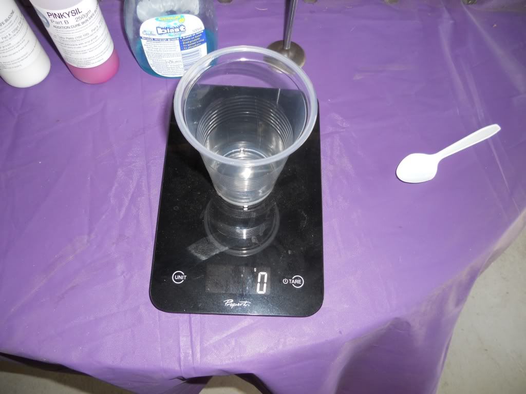
Place the cup on the scale.
Image


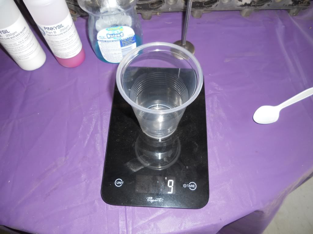
and then zero the scale
Image


Slowly pour in 80 grams of PART A
Image

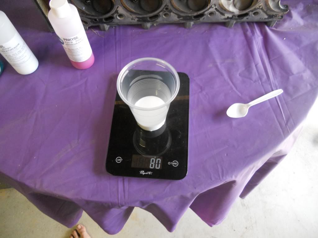
Then aero the scale again.
Slowly pour in 80 grams of PART B

Mix thoroughly to get an even, consistent coulor. At this point as we are using a fast set silicon you only have at most ONE minute to get the mixing done other wise the silicon will start to set and you will be rushing to pour the now thick lumpy silicon before it's wasted. TRUST ME

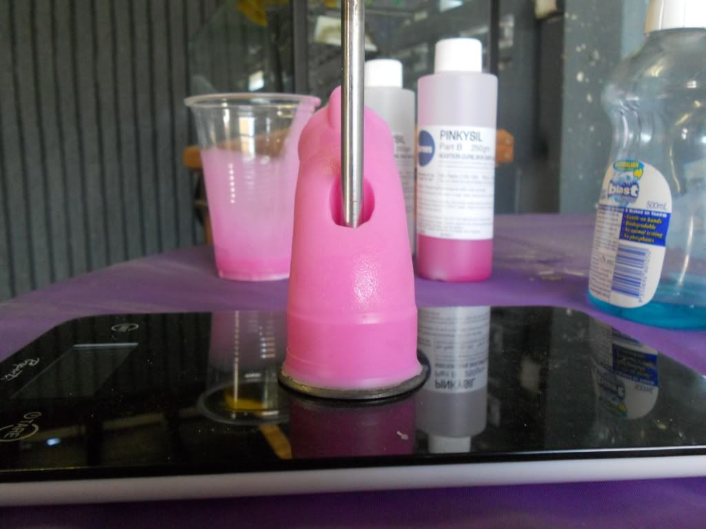
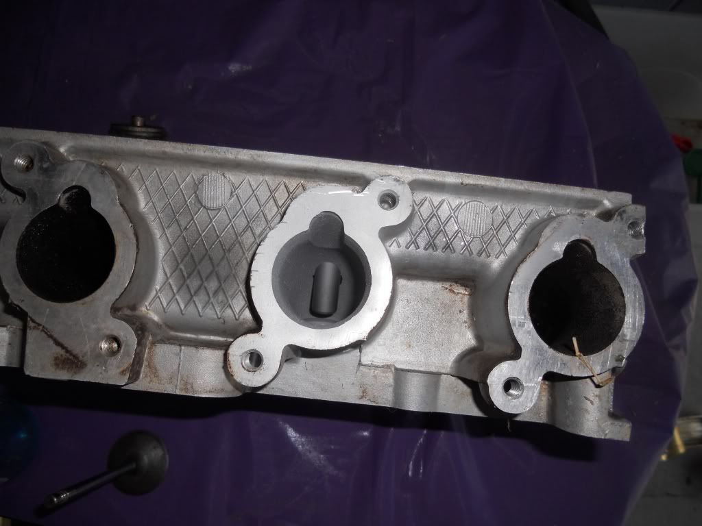
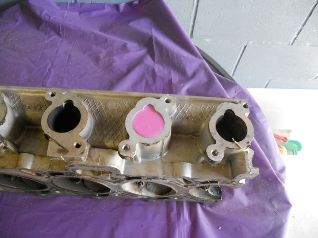
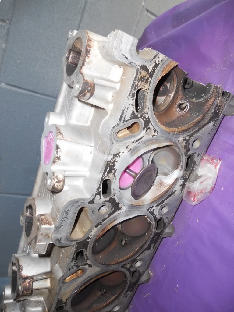
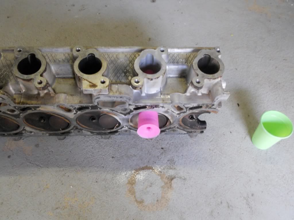
Once mixed pour the silicon slowly into the port until full
Image

Depending on the head you are moulding, you'll have a little left over
Image
If you have a lead sinker moulds, now would be a good time for making some bright pink slingshot ammo
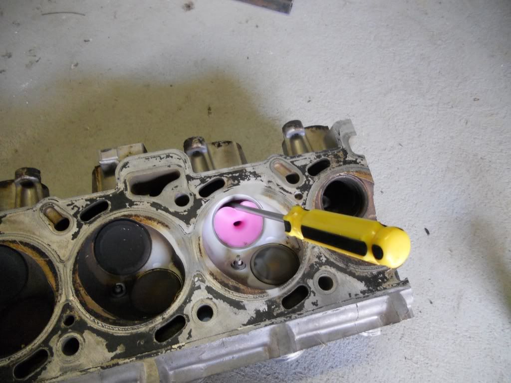

De-moulding

After 20 mins the mould is ready to come out.
Give the valve a tap to knock it loose and remove it.
Image
Image


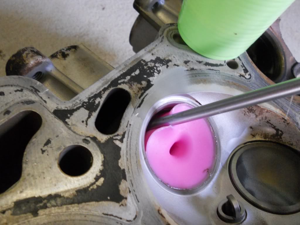
Insert a flat screw driver to gently pry the mould away from the port walls, do this right around the mould at both ends.
Image
Image

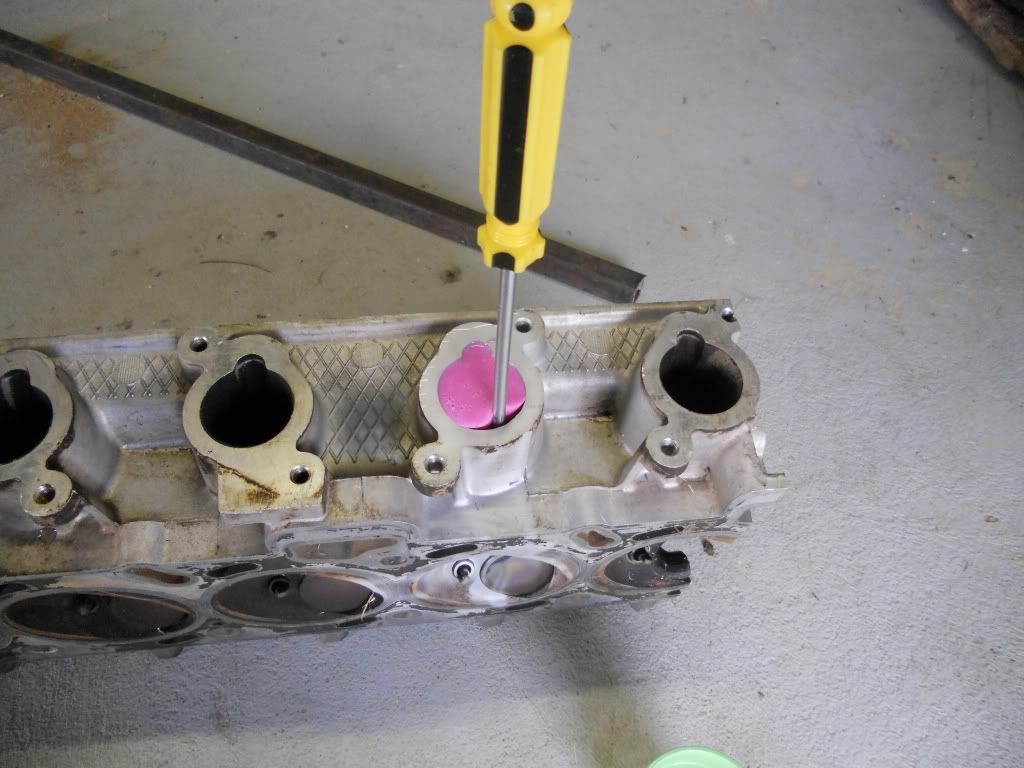
Mix a small amount of water and dish liquid and with the screw driver still inserted tip some into the gap, again all around and at both ends working the mould to get all of it soaked.
Image
Image

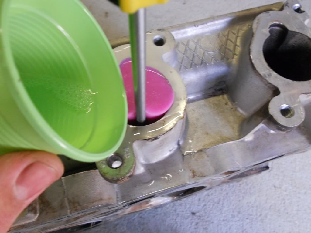
Now push from the manifold end with handle of the screw driver and push the mould out.
This may take a fair amount of force.
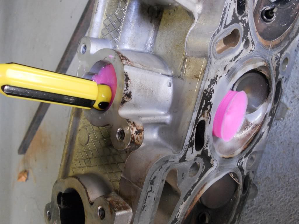
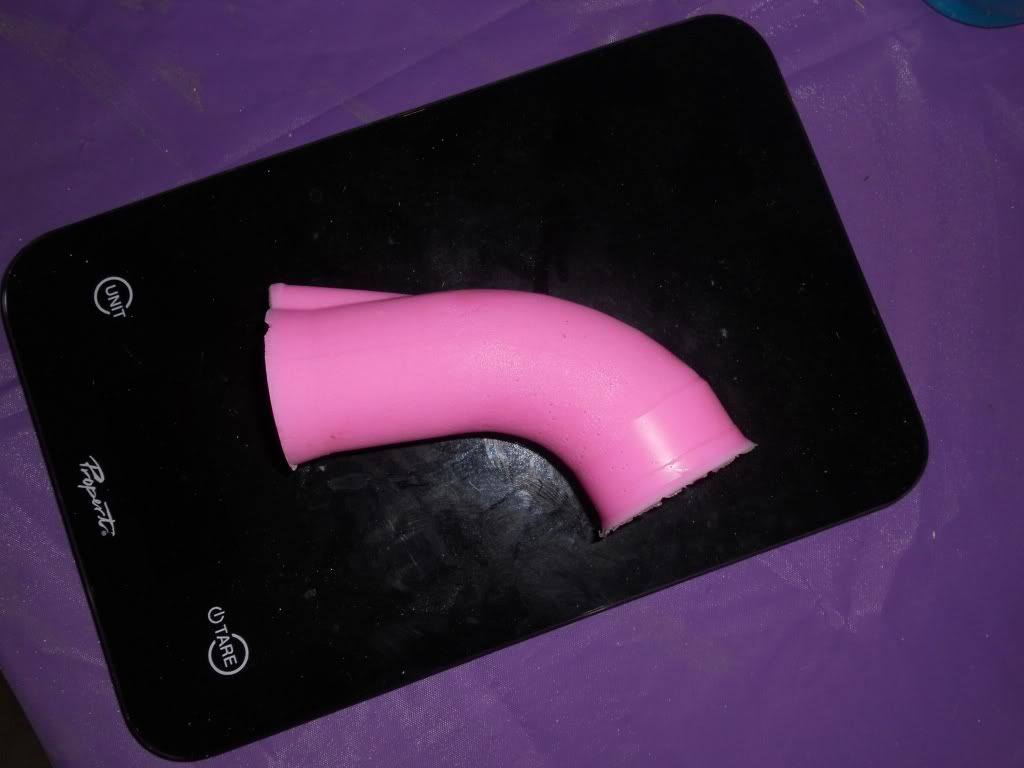
Image
Image


The finished mould
Image
Image
If you follow this advice and 'the dyno' can't 'give you what you wanted'. Remember one thing, I don't give a shit what 'the dyno' says.
Before you diagnose yourself with depression or low self esteem, first ensure you are not, in fact, just surrounded by arseholes!
User avatar
brad_m
Cruising
 
Posts: 417
Joined: January 19th, 2011, 8:14 pm
Location: Townsville
Has Liked: 9 times
Been Liked: 56 times

Re: Making a Silicon Port mould

Postby holmsy » September 25th, 2011, 11:21 pm

whats the use of this?
Project: SLOXR8: 1994 EF XR8, mech shift kit, 3500 histall, Lokka, 36lb injectors, AU 185 motor, Cranecam 444225, crane roller rockers, crow valve springs, Pacies, 3" exhaust, hiflo cats. twin 044's, vortech v2,microtech tuned by daltons (290.3rwkw @11psi) at DALTONS
Image
User avatar
holmsy
Shooting Flames
 
Posts: 6473
Joined: August 2nd, 2007, 11:07 pm
Location: Geelong
Has Liked: 182 times
Been Liked: 154 times

1994 Ford XR8

Re: Making a Silicon Port mould

Postby misk » September 25th, 2011, 11:36 pm

i'd say to help with porting, to see the shape of the port better.
XG Panelvan
EF bottom end with ported EB head, valve springs, EL ECU & J3 chip, crane HI6 CDI & MSD coil, LC-1 wideband & SSI-4 logger

soon - .595" lift cam, GT4202, forged AU engine and built head, ems stinger 4424 ecu, powerglide with 5500 high stall etc - next, bellhousing

XH ute daily - DOHC BA XR6 engine, T5, AU3 ECU with TI J3 chip, ported BBM, 3" stainless intake - 12" sub, tub liner and hard lid - mass skids and epic tyre carrying capabilities :)
User avatar
misk
Melting Pistons
 
Posts: 10047
Joined: October 14th, 2008, 10:31 am
Location: dandenong
Has Liked: 298 times
Been Liked: 295 times

Re: Making a Silicon Port mould

Postby SL33PNcoons » September 26th, 2011, 12:07 am

He's fabricating marital aids But nice. I will do this with my ported head while its off the car if you like? EF tickford stage III port job by hoppers express. see what you think.
EFII Futura Turbo 5sp
BF MKII XR6T- build ZF6sp-400rwkw
T2 FTE TE50 #068
R34 GT-Four-RB26 400awkw
User avatar
SL33PNcoons
Cruising
 
Posts: 203
Joined: September 9th, 2010, 8:53 pm
Has Liked: 6 times
Been Liked: 10 times

1996 Ford Falcon

Re: Making a Silicon Port mould

Postby brad_m » September 26th, 2011, 6:35 am

SL33PNcoons wrote:He's fabricating marital aids But nice. I will do this with my ported head while its off the car if you like? EF tickford stage III port job by hoppers express. see what you think.


That would awsome, thanks.
If you follow this advice and 'the dyno' can't 'give you what you wanted'. Remember one thing, I don't give a shit what 'the dyno' says.
Before you diagnose yourself with depression or low self esteem, first ensure you are not, in fact, just surrounded by arseholes!
User avatar
brad_m
Cruising
 
Posts: 417
Joined: January 19th, 2011, 8:14 pm
Location: Townsville
Has Liked: 9 times
Been Liked: 56 times

Making a Silicon Port mould

Postby TUFED6 » September 26th, 2011, 10:49 am

Wow pretty cool shit. What have been your findings so far?
User avatar
TUFED6
Full Boost
 
Posts: 2926
Joined: July 13th, 2007, 12:21 pm
Location: I put the fuk into shima
Has Liked: 2 times
Been Liked: 434 times

1994 Ford Falcon

Re: Making a Silicon Port mould

Postby brad_m » September 26th, 2011, 5:18 pm

That particular port (AU1 VCT) narrows at the short turn and has the valve guide protruding at the same point creating a choke point.
The choke point is what limits flow at high lifts, below roughly .350" lift the shape of the valve, seat ect is what controls flow.

Until the choke is fixed puting grinding burr or paper roll anywhere between the port entry and the start of the short turn is waste of time.

For the DIYer the time and money best spent is removing the guides and shortening them by 3mm (using the shortest one as a guide to modifying the others) then tappering them down. 30 degree back cut on the valves, taking the seat width down to 80thou and then having the the seat in the head cut to make the contact area right the in the centre of the seat on the valve. A good machine shop will know what you are talking about.

If you must grind something, widen the port around the guide and the blend all of the rough maching in the bowl of the port.
For beginners the blending is best done with a flap wheel as it's hard to make big mistakes with them, then take the pollish off with a 60 grit cartridge roll.


That's about all I would recomend a beginner does on any of the I6 heads.
If you follow this advice and 'the dyno' can't 'give you what you wanted'. Remember one thing, I don't give a shit what 'the dyno' says.
Before you diagnose yourself with depression or low self esteem, first ensure you are not, in fact, just surrounded by arseholes!
User avatar
brad_m
Cruising
 
Posts: 417
Joined: January 19th, 2011, 8:14 pm
Location: Townsville
Has Liked: 9 times
Been Liked: 56 times

Re: Making a Silicon Port mould

Postby XR_Lightning » September 26th, 2011, 7:02 pm

cool idea, defintely interesting
ED XR6 - T5 - 1521a@112 - 3.9's - 170.2rwkw - POWERED BY METALLICA
User avatar
XR_Lightning
Hitting N2O
 
Posts: 3716
Joined: July 23rd, 2007, 6:48 pm
Location: Dandenong North
Has Liked: 1076 times
Been Liked: 487 times

1993 Ford ED Falcon XR6

Re: Making a Silicon Port mould

Postby brad_m » September 27th, 2011, 8:34 pm

holmsy wrote:whats the use of this?


Here is the reason I moulded that port.


Autospeed flow a STOCK AU head at 117cfm at .500" lift. They tested it at 10" H2O
To convert from 10" to 28" we mutiply by 1.67.
That puts the AU head 195.39cmf@.500" lift tested at 28" H20.

Now if we work back to the MCSA of the port at the choke point in the turn(MCSA = min cross-sectional area) .
The MCSA is 864mmsq.
Through some math we can use that to show us what flow the MCSA will support with an air speed of 350fps. When I do this I get 195.494CFM @ 28" H2O. (those findings prove the formula)

IF we then work our way through the port,
The port proper can support 230cfm
The seat area can support 281cfm
Curves, shape change, and other things will effect the flow. Meaning if you didn't touch the seat area at all and brought the rest of the port to a point that it could flow 280cfm you probably will not get 280 through the seat.
If you follow this advice and 'the dyno' can't 'give you what you wanted'. Remember one thing, I don't give a shit what 'the dyno' says.
Before you diagnose yourself with depression or low self esteem, first ensure you are not, in fact, just surrounded by arseholes!
User avatar
brad_m
Cruising
 
Posts: 417
Joined: January 19th, 2011, 8:14 pm
Location: Townsville
Has Liked: 9 times
Been Liked: 56 times

Re: Making a Silicon Port mould

Postby mad_keen » October 10th, 2011, 6:37 pm

Wouldnt porting everywhere until you cant port no more be the best?
Image
User avatar
mad_keen
Full Boost
 
Posts: 2000
Joined: December 15th, 2008, 9:15 pm
Location: FNQ
Has Liked: 25 times
Been Liked: 44 times

1996 Ford Falcon

Re: Making a Silicon Port mould

Postby SNR » October 11th, 2011, 11:17 am

Until you can port no more? I.e. when you hit a water or oil jacket? Ideally you want a port that promotes flow. Just opening up "everywhere" means you have areas that the port drops in pressure, which would slow down or distort the flow
Straights are for fast cars... Turns are for fast drivers

http://www.flickr.com/photos/silencer_rh - View My Photos on Flickr.com
http://www.boostedfalcon.net/viewtopic.php?f=3&t=7390 - My EBII Fairmont Sickmachine.
http://www.e21build.com - My BMW E21/Ford 4.0 I6 Drift/Rally Project Car
SNR
Full Boost
 
Posts: 2830
Joined: July 19th, 2007, 6:47 pm
Location: Warrnambool, VIC
Has Liked: 174 times
Been Liked: 100 times

Re: Making a Silicon Port mould

Postby brad_m » October 13th, 2011, 7:31 pm

mad_keen wrote:Wouldnt porting everywhere until you cant port no more be the best?


No because you would end up with a bad shape and to much variation in CSA and also to much CSA resulting in low air speed.
If you follow this advice and 'the dyno' can't 'give you what you wanted'. Remember one thing, I don't give a shit what 'the dyno' says.
Before you diagnose yourself with depression or low self esteem, first ensure you are not, in fact, just surrounded by arseholes!
User avatar
brad_m
Cruising
 
Posts: 417
Joined: January 19th, 2011, 8:14 pm
Location: Townsville
Has Liked: 9 times
Been Liked: 56 times

Re: Making a Silicon Port mould

Postby mad_keen » October 13th, 2011, 7:32 pm

Thanx for clearing that up :good:
Image
User avatar
mad_keen
Full Boost
 
Posts: 2000
Joined: December 15th, 2008, 9:15 pm
Location: FNQ
Has Liked: 25 times
Been Liked: 44 times

1996 Ford Falcon


Return to Tutorials

Who is online

Users browsing this forum: No registered users